Basic Understanding Of Virtual Switching System.
In this article, we are going to discuss the VSS feature which is a Cisco proprietary. The following topics will be covered in this blog:
- What is VSS?
- Benefits of VSS
- How VSS works?
What is VSS?
VSS stands for Virtual Switching System. It is used to create one logical switch by combining two physical switches. It is a Cisco proprietary. This feature is supported on Catalyst 4500 & 6500 modular switches.

Benefits of VSS

If we compare the above network architectures, we can see the following advantages of using VSS over traditional network architects:
- In a traditional network architect, only one uplink can be utilized at a time due to the STP loop avoidance mechanism, but with VSS, all uplink bandwidth can be utilized.
- The traditional network architect may look a bit complex while connecting multiple Access Layer switches to the distribution or core layer switch in redundancy. VSS reduces the complexity of the network architect.
- In traditional network architect, we have required the gateway’s redundancy configuration at the distribution/core layer by using FHRP. With VSS, the need for FHRP gets eliminated and hence we can utilize full bandwidth.
How VSS works?
VSS works on Cisco IOS Stateful Switch Over (SSO) & Non-Stop Forwarding (NSF) technologies. We have just required some basic configurations on individual chassis and reloaded them for clustering two physical chassis to act as a single logical chassis with VSS.
In a Cisco Virtual Switching System, one chassis is designated as the active virtual switch and the other is designated as the standby virtual switch. All control plane functions are centrally managed by the active virtual switch including the following:
- SNMP, Telnet, SSH, etc.
- Layer 2 protocols (BPDU, LACP, etc.)
- Layer 3 protocols (RIP, OSPF, etc.)

From plain data and traffic forwarding perspectives, both switches in the Virtual Switching System actively forward traffic.
In order to bond the two switches into one logical chassis, the control information must be exchanged between the two chassis in a timely manner. To facilitate this information exchange, a dedicated link is used to transfer both control plane & data plane traffic between the peer chassis. This link is referred to as the virtual switch link (VSL).
Virtual Switch Link (VSL):

Both control & data traffic is carried out on this Virtual Switch link. All frames that are sent across the VSL are encapsulated with a Virtual Switch Header (VSH), which is added directly before the Ethernet Header to the frame by the egress port and stripped off on the other side of the VSL by the ingress port. It is 32 bytes long.

To make sure that control traffic gets the highest priority across the VSL, a special bit is set on all VSL control frames. This helps ensure that these frames always get priority from both ingress and egress hardware queues.
Virtual Switch Link Initialization:
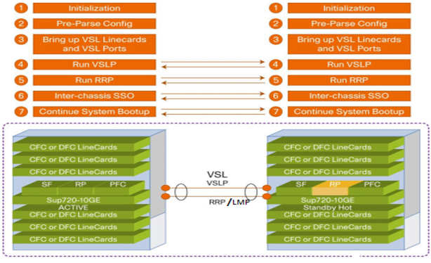
The VSS initialization process must determine which chassis switch will become active for the VSS. In order to determine the chassis active & standby roles, the Virtual Switch Link (VSL) must be initialized and UP for control plane communication.
The following VSL initialization steps are involved:
- Bring up VSL interfaces
- Link Management Protocol (LMP)
- Role Resolution Protocol (RRP)
Bring up VSL interfaces:
The supervisor CPU determines which ports are the members of VSL. The configuration file is prepared to extract the appropriate VSL commands with associated interfaces.
This way, the modules containing these interfaces can be powered up and VSL interfaces brought online.
Link Management Protocol (LMP):
The Link Management Protocol operates on Virtual Switch Link (VSL) and is part of Virtual Switch Link Protocol (VSLP).
The LMP performs the following functions:
- Verifies link integrity
- Exchanges switch chassis IDs between the chassis
- Exchanges other information required to establish communication between the two chassis
Role Resolution Protocol (RRP):
The redundancy role of each chassis switch is resolved Role Resolution Protocol (RRP) and is part of Virtual Switch Link Protocol (VSLP).
The RRP performs the following functions:
- Determines whether the hardware and software versions allow a VSS to be formed or not
- Determines which chassis will become the active virtual switch and which will become the standby virtual switch chassis from a control-plane perspective.

The above diagram shows the summary of Virtual Switching System (VSS) initialization.
In this article, we have learned the basic concept of VSS. We learned the benefits of using VSS in our network environment and knew the supported platform for VSS. We also learned, how VSS initialization works to act as a single logical switch. In the next part of this blog, we will cover the VSS configuration and the prerequisite for configuring VSS on a device. To get the right IT Consultation, give us a call on +919773973971 or drop us a mail to get in touch with us.
Author
Sani Singh
Consultant – Enterprise Networking
