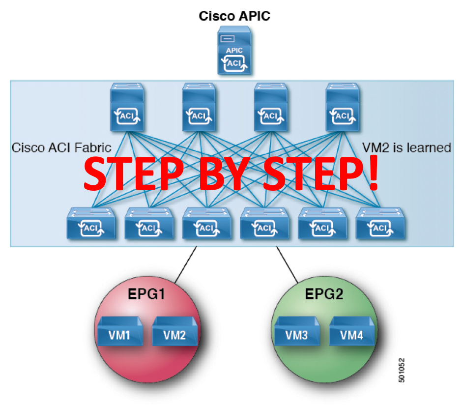
How to configure Cisco ACI Part 2 of 2
In the last part of this series on configuring Cisco ACI, we brought up the physical domain and created basic logical constructs such as VLANs, tenants, bridge domains, etc. In this part, we’ll go deeper and create policies (global, Attachable Access Entity profiles, interface policies, link level policies, CDP interface policies, etc). We’ll also look at VPC config, and leaf switch policies and profiles. Here’s the table of contents once again. We’re resuming from step 15.
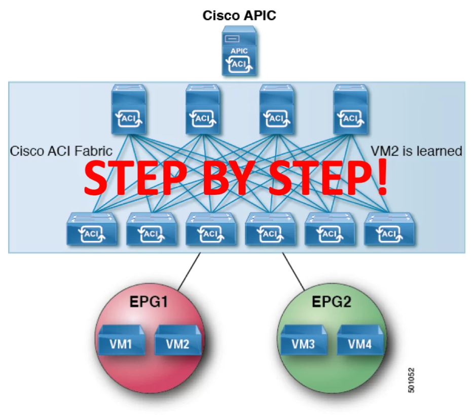
Table of Contents
- What is Cisco ACI
- Initial Start-up configuration
- Fabric Discovery and Node registration
- Upgrade the fabric
- Add Image to APIC
- Upgrading Device
- Creating Tenant
- Create Application Profile
- Create Bridge Domain
- Creating EPG ( END POINT GROUP)
- ADD Domain in EPG
- Assign Static Ports IN EPG
- Creating VLAN Pool
- Creating Physical Domain
- Create Policies
- Configuring Cisco ACI – Create Global Policies
- Create Attachable Access Entity Profiles
- Create Interface policies
- Link Level policies
- Create CDP Interface Policies
- LLDP Interface Policies
- Port Channel Policies
- Switch Policies
- Configuring Leaf Interfaces
- Leaf Interface Policy group
- Create Leaf Access Port
- Port Channel Interfaces
- Virtual Port-Channel Interface (VPC)
- Leaf Interface Profiles
- Configuring Cisco ACI – Configuring Leaf switch
- Leaf Switch Policy Group
- Leaf Switch Policy Group
- Leaf Switch Profiles.
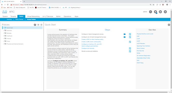
Configuring Cisco ACI – Create Policies
Create Global Policies
Create Attachable Access Entity Profiles
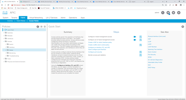
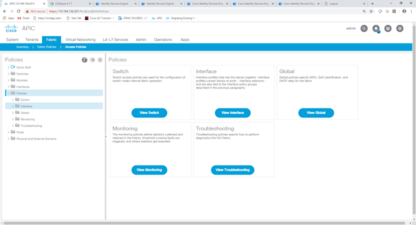
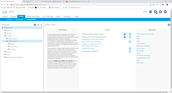
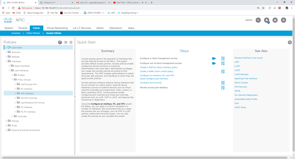
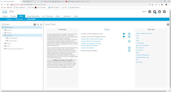
Step 1:- Go to Fabric Tab > Access Policies
Step 2 :- Go to policies
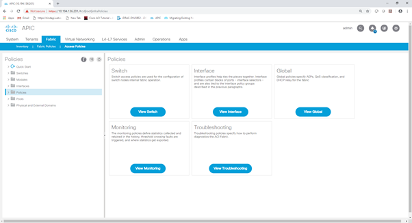
Step 3 :- Click the Navigator and go to the global
Step 4 :- Click on the Global navigator and go to the Attachable access entity profile.
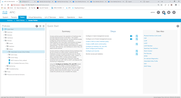
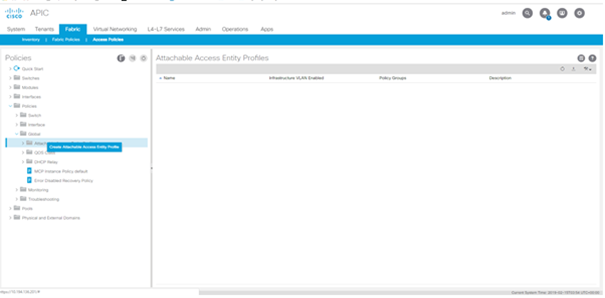
Step 5 :- Right click on Attachable access entity profile and create Attachable access entity profile.
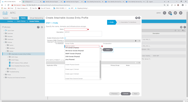
Step 6 :- In step 1 > Profile enter the Name and go to the Domain to be associated tab and click + button.
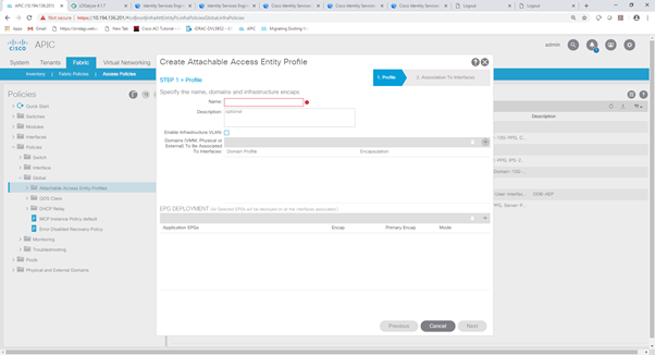
Step 7 :- Select the domain from dropdown menu which you have created earlier and click on update and then Next.
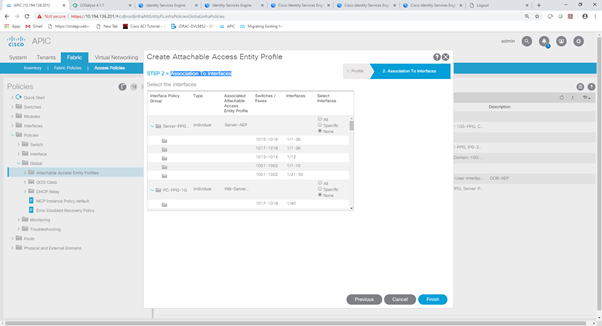
Step 8 :- In Step 2 > Association To Interface you can select the interface if you have configured the interfaces or you can skip this step and map this AEP with interface later. Click on Finish button.
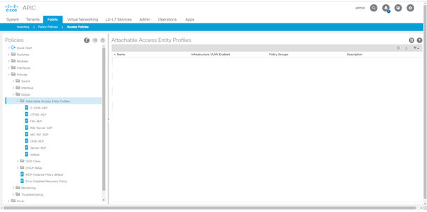
Step 9 :- You can see the configured AEP on right side window and click on AEP profile Navigator you can see in Navigator panel as well.
Create Interface policies
Link Level policies
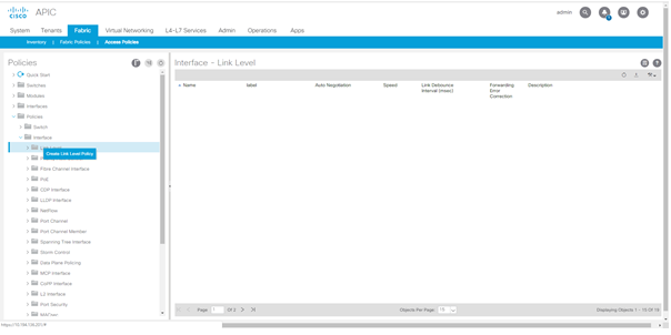
Step 1 :- Go to Fabric tab > Access policies > policies click on Navigator and go to interfaces.

Step 2 :- Click on interface Navigator and go to the link level interface policy.
Step 3 :- Right Click on link level and click on Create Link Level Policies
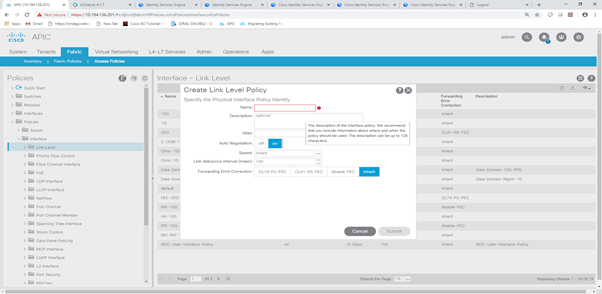
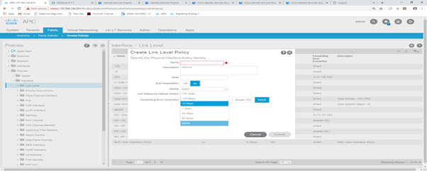
Step 4 :- Enter the name and select the interface speed from dropdown and interface negotiation mode and click submit.
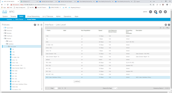
Step 5 :- You can see the created Link Level policy in right side window and you can click on link Level Navigator and you will see all the link level policies in navigator section as well.
Create CDP Interface Policies
Step 1 :- Go to Fabric tab > Access policies > policies click on Navigator and go to interfaces.

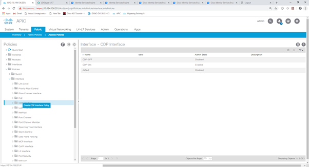
Step 2 :- Click on interface Navigator and go to the CDP interface policy.
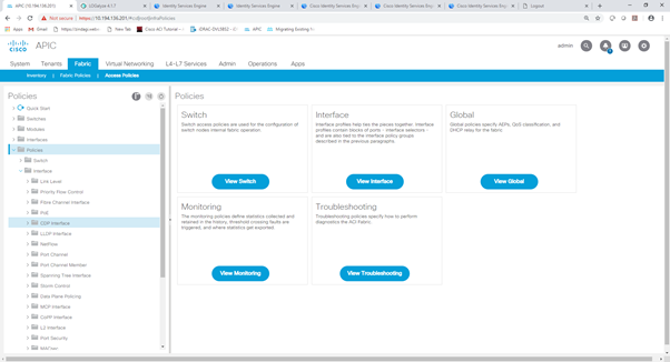
Step 3 :- Right click on CDP interface and click on create CDP interface policies.
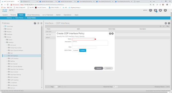
Step 4 :- Enter the Name and select the Admin State and submit.
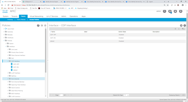
Step 5 :- You can see created CDP policies in right side window and you can see the policies in navigator section as well after click the CDP navigator.
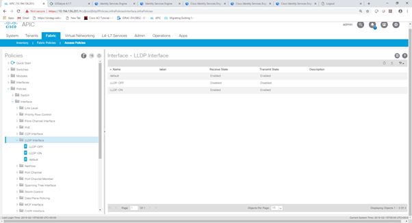
LLDP Interface Policies
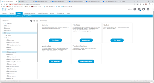
Step 1 :- Go to Fabric tab > Access policies > policies click on Navigator and go to interfaces.
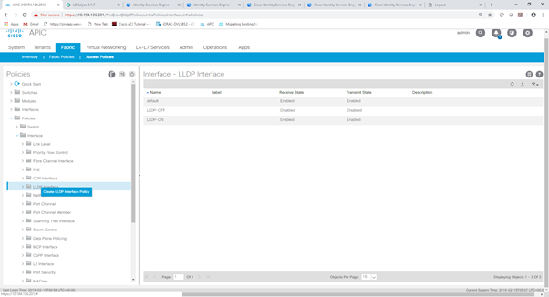
Step 2 :- Click on interface Navigator and go to the LLDP interface policy.
Step 3 :- Right click on LLDP interface and click on create LLDP interface policies.
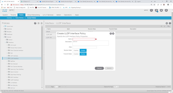
Step 4 :- Enter the Name and select the Receive State, Transmit state and submit.
Step 5 :- You can see created LLDP policies in right side window and you can see the policies in navigator section as well after click the LLDP navigator.
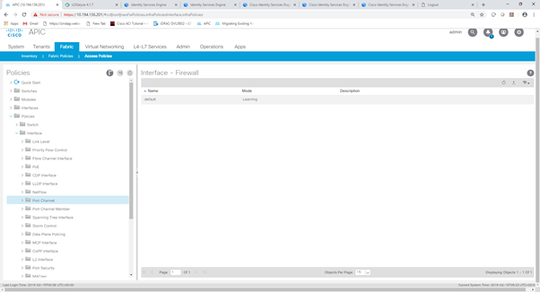
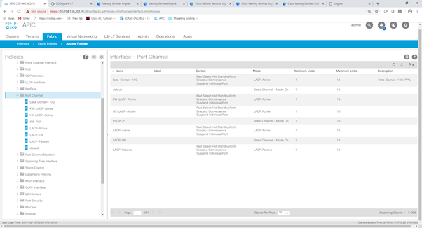
Port Channel Policies
Step 1 :- Go to Fabric tab > Access policies > policies click on Navigator and go to interfaces.

Step 2 :- Click on interface Navigator and go to the Port Channel policy.
Step 3 :- Right click on Port Channel and click on create Port Channel policies.
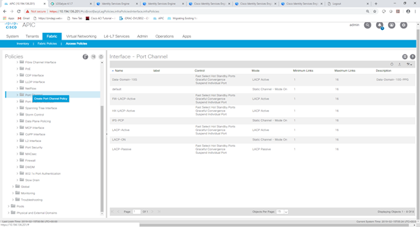
Step 4 :- Enter the Name and select the mode from dropdown and submit.
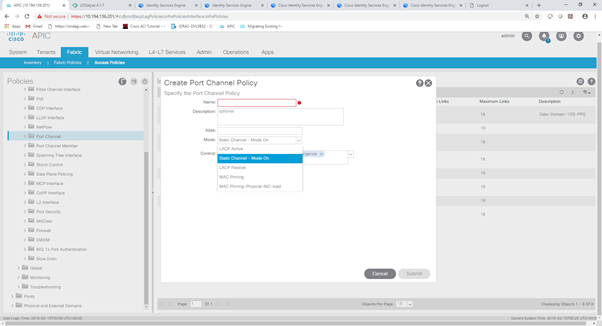
Step 5 :- You can see created Port Chanel policies in right side window and you can see the policies in navigator section as well after click the Port Channel navigator.
Note :- You Can create all the policies which will be needed for the interface you can create all the policies here same as previous policies and during interface configuration time you can call these policies as needed.
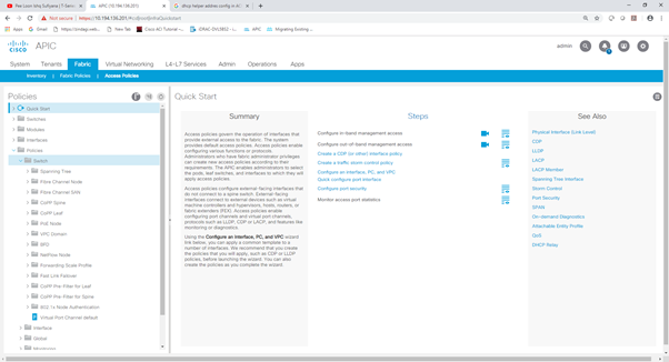
Switch Policies
You can make All the switch protocol related configuration here like, Spanning tree , CoPP SPAN, BFD, 802.1x Authentication etc.
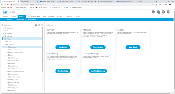
Step 1:- Go to Fabric Tab > Access Policies

Step 2 :- Go to policies

Step 3 :- Click the Navigator and go to the Switch
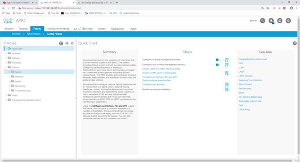
Step 4 :- Click on the Switch Navigator and you will see all the switch protocol here. You can configure any protocol.
Configuring Cisco ACI – Configuring Leaf Interfaces
In this section you will configure all the switch interfaces related configuration.
Leaf Interface Policy group
In this section you will create the interface policy group in we call the interface policies which we configured earlier in policies Section.
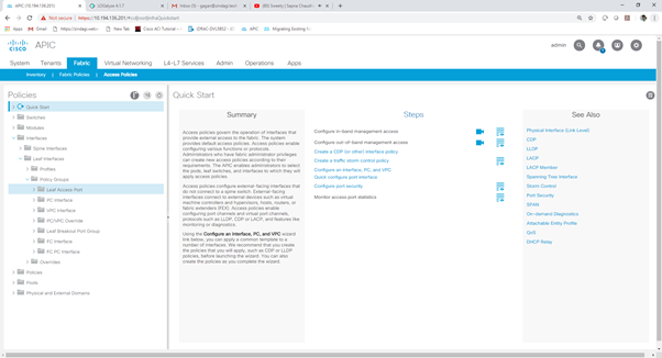
Step 1 :- Go to Fabric tab > Access policies > Interfaces.
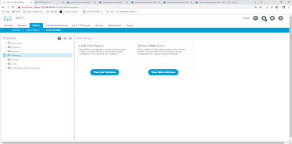
Step 2 :- Click on Interface Navigator.

Step 3 :- In this it will depend which switch you want to configure either Spine of Leaf switch. Here i’ll configure Leaf switch.
Click on Leaf switch Navigator and go to Policy group.
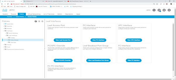
Create Leaf Access Port
Step 1 :- Click on Policy Group Navigator and go to Leaf Access Port.
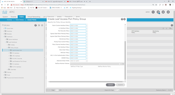
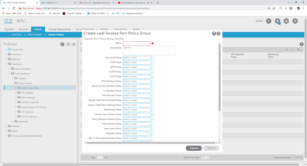
Step 2:- Right click on leaf access port and create leaf access port policy group.
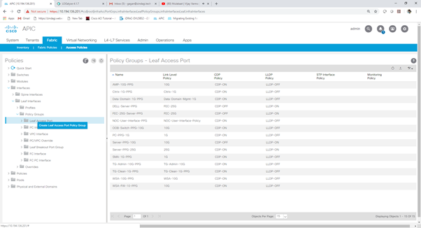
Step 3 :- Enter the Name and the port policies from dropdown. Which you configured earlier in Policies section and submit.

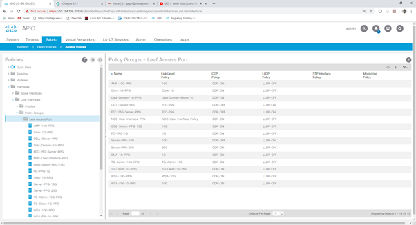
Step 4 :- You can see created leaf access port policy group in right side window and you can see the PPG in navigator section as well after click the leaf access port navigator.
Port Channel Interfaces
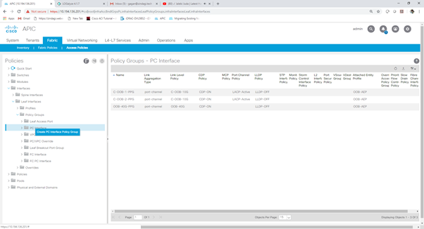
Step 1 :- Click on Policy Group Navigator and go to PC Interface.

Step 2:- Right click on PC Interface and create PC Interface port policy group.
Step 3 :- Enter the Name and the port policies from dropdown. Which you configured earlier in Policies section and submit.


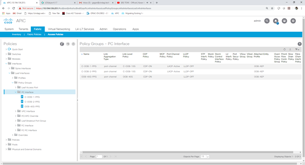
Step 4 :- You can see created PC Interface port policy group in right side window and you can see the PPG in navigator section as well after click the PC Interface navigator.
Virtual Port-Channel Interface (VPC)
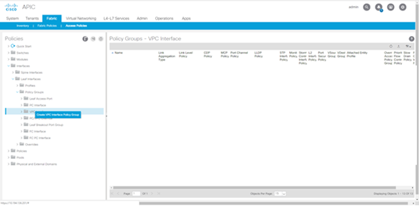
Step 1:- Click on Policy Group Navigator and go to VPC Interface.
Step 2:- Right click on VPC Interface and create VPC Interface port policy group.
Step 3 :- Enter the Name and the port policies from dropdown. Which you configured earlier in Policies section and submit.

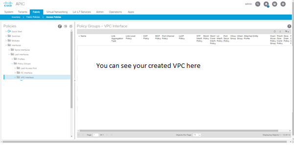
Step 4 :- You can see created VPC Interface port policy group in right side window and you can see the PPG in navigator section as well after click the VPC Interface navigator.
Note :- You Can create all the Port Policy Group which will be needed to interface you can create all the policies here same as previous policies and during interface configuration time you can call these policies as needed.
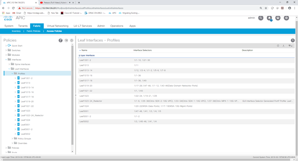
Leaf Interface Profiles
In this section you will create the interface profiles in this we’ll call the interface policy group which we configured earlier in policy group Section.
Step 1 :- Step 1 :- Go to Fabric tab > Access policies > Interfaces.

Step 2 :- Click on Interface Navigator.
Step 3 :- In this it will depend which switch you want to configure either Spine of Leaf switch. Here i’ll configure Leaf switch.
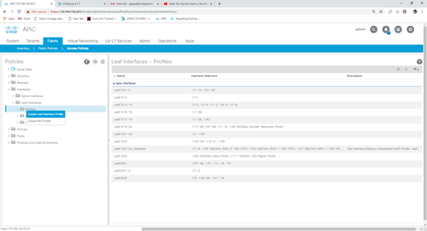
Click on Leaf switch Navigator and go to Profiles.


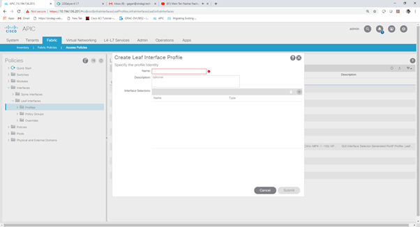
Step 4 :- Right Click on Profiles and create Leaf Interface Profile
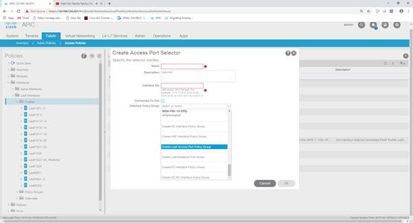
Step 5 :- Enter the Name and go to Interface Selector and click on + icon.
Step 6 :- Enter Name And Interface ID and go to Interface Policy Group and select policy group from Dropdown click OK and Submit.
Step 7 :- You can see created Leaf Interface Profiles in right side window and you can see the Leaf Interface Profiles in navigator section as well after click the Profiles navigator.
Configuring Cisco ACI – Configuring Leaf switch
Configuring Cisco ACI – Leaf Switch Policy Group
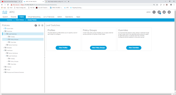
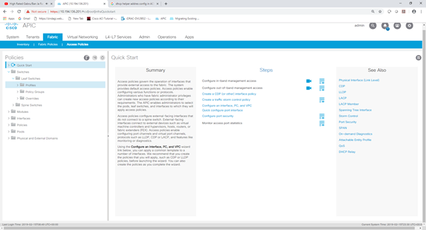
Step 1 :- Go to Fabric tab > Access policies > Switches
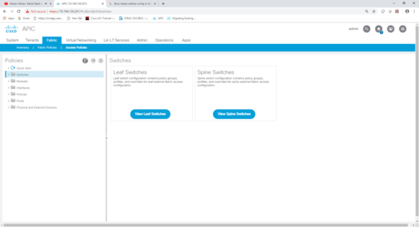
Step 2 :- Click on Switch Navigator and expand it.
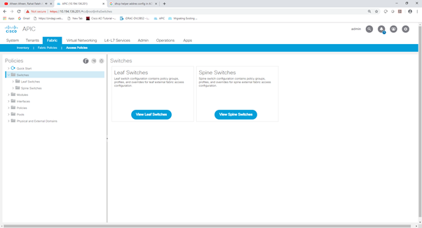
Step 3 :- In this it will depend which switch you want to configure either Spine of Leaf switch. Here i’ll configure Leaf switch.
Click on Leaf switch Navigator and go to Policy group.
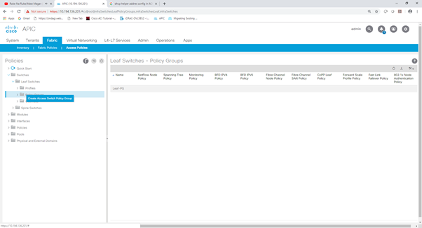
Configuring Cisco ACI – Leaf Switch Policy Group
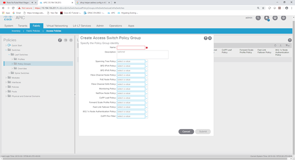
Step 1 :- Right Click on Policy Group and Create Access switch policy group
Step 2 :- Enter the name and select all the policy from dropdown which you have configured earlier under Policies > switch policies section and submit.
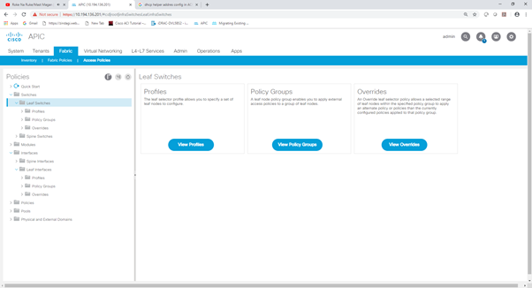
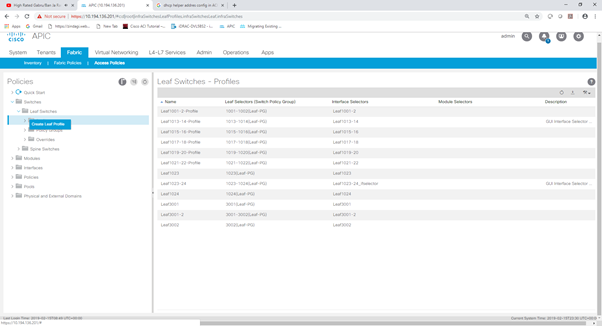
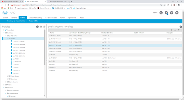
Configuring Cisco ACI – Leaf Switch Profiles.
Step 1 :- Go to Fabric > Access Policies > Switch >Leaf switch >profiles.
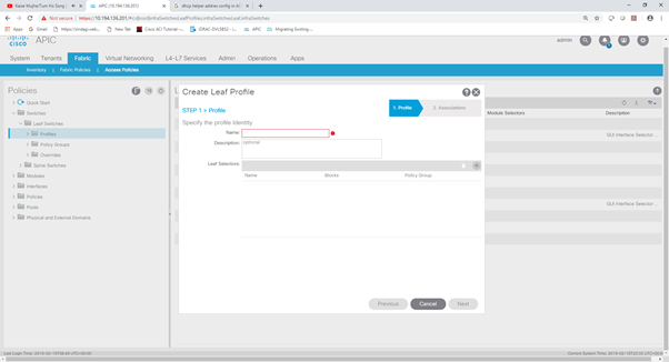
Step 2 :- Click on profile Navigator and Create Leaf Profile
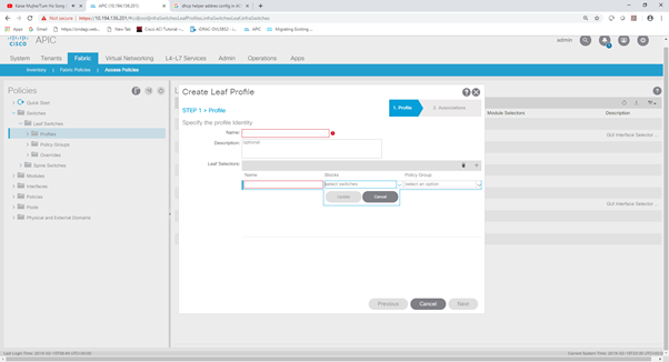
Step 3 :- In step 1 > profile enter name and go to the Leaf selector and click on + button to select the leaf.
Step 4 :- Enter name and select leaf form dropdown and select the policy group from dropdown as well which you configured earlier under switch > policy group and click update and Next.
Step 5 :- In step 2 > Association you can select the Interface selector Profile which you configured under Interface > Leaf Interface > profiles or you can leave this and click on finish.
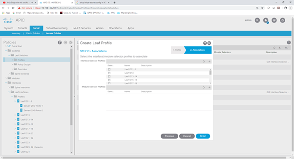
Step 6 :- You can see created Leaf Switch Profiles in right side window and you can see the Leaf Switch Profiles in navigator section as well after click the Profiles navigator.
Summary – Configuring Cisco ACI
Hope you found this two part series useful and that it will save you some time when doing an ACI deployment for your customers.
Are you looking for advisory, consulting and professional services that will help you meet your Information Technology goals? Zindagi can help!
Zindagi Technologies is an IT consultancy and professional services organisation based out of New Delhi, India. We’re experts in large scale data centre design and deployment, service provider network design, information security, blockchain, IoT, Smart Cities, and Private/Public/Hybrid cloud solutions. Each one of us has years of experience in large scale network design, deployment and automation. Our “customer first” motto drives us forward, and we believe in providing quality services to our clients always.
Contact us now, to know how Zindagi can help solve your IT / Information Security related problems. We’re also available on email and phone (India business hours).
Author

Consulting Engineer
Zindagi Technologies LLP