10 Easy Steps to Configure Service Profiles in UCS Manager
Cisco’s UCS Manager is a Software-Defined Data Center (SDDC) solution that provides us a single pane of glass to provide simplified management of our servers and chassis. UCS Manager allows you to configure/manage your blade chassis, blade servers, rack servers, etc. in a single UCS domain.
What exactly is a UCS domain? – Fabric Interconnects which is our TOR switch for blade chassis, defines the UCS domain. The UCS Manager software which happens to be the brain of Cisco’s SDDC solution sits inside these Fabric Interconnects. The number of blade chassis that can be managed by an instance of UCS Manager, draws the boundary of the UCS domain. A single UCS domain can grow up to as many as 20 blade chassis.
Service Profiles – The What?
UCS Manager helps us achieve stateless computing with one of its key components – Service Profiles. A server’s identity is all about its MAC Addresses for vNICs, WWPN for vHBAs, UUID, etc. You can abstract all these key identifiers and play around by packaging them in one profile and moving this pre-packaged identity from one blade server to another, this is called stateless computing.
The Service Profiles are stored in the Fabric Interconnects and then pushed to the servers in a UCS domain. You can mix and match servers of different generations/models in a UCS environment. The configuration constructs are totally independent of the underlying hardware.
There Are Two Types Of Service Profiles:
Service Profile Which Inherits Server Identity: These type of service profiles uses the burned-in factory settings and values like MAC address, WWPN, BIOS version, etc. Since we use burned-in values of the servers, it pretty much justifies that this type of service profile is more suitable for 1:1 mapping configuration. These types of service profiles cannot be moved from one server to another as they would require changes to be in certain parameters at the time of porting.
Service Profile Which Overrides Server Identity: This type of service profile exhibits the true nature of stateless computing as it uses identity parameters like MAC addresses, WWPN, BIOS version, Disk Configuration, Firmware maintenance, etc. from a pool of resource configured inside UCS Manager. These type of service profiles provides us with 1: many mapping capabilities and can be moved from one server to another.
UCS Manager provides you an option on how you would like to create a service profile. You can either create a single instance of Service Profile via a basic configuration wizard (It inherits server identity) or you can create a template and generate several Service Profiles from it (It overrides server identity). If you wish to choose the latter then you may want to create several pools for attributes like IP Addresses, UUID, MAC Addresses, etc. We will go through the steps on how to create a Service Profile Template like a Pro!
Service Profile – The How?
There are a lot of customizations that you can do while creating a Service Profile Template. In this blog, we will cover a few yet basic topics that you may want to gather before proceeding with Service Profile Template creation. At first, you would want to create several pools and policies for the following components:
- UUID pool
- MAC Address pool
- OOB IP Address pool
- Local Disk Configuration Policy
- Host Firmware Package
- Maintenance policy
- WWPN Pool
- vNIC Templates for both the Fabrics
- vHBA Templates for both the Fabrics
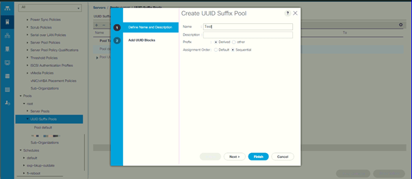
Step 1- UUID pool: UUID is also called Universal Unique IDentifier. UUID is a 128-bit value formatted into blocks of hexadecimal digits. This will be the server’s ID and it will be unique to every blade server in a UCS domain.
To create a UUID pool, navigate to Servers > expand Pools > right-click UUID Suffix Pool > select Create UUID Suffix Pool. A new dialog box would open, key in the name of your UUID Suffix Pool and select assignment order and click Next. On the next screen, you would require clicking on Add icon to create a UUID block. Click Finish to create the UUID Suffix Pool.
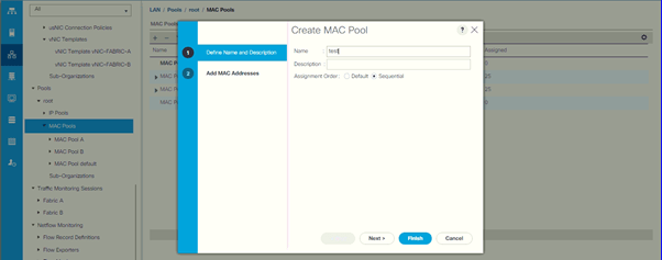
Step 2 – MAC Address Pool: MAC address pool will be later mapped to the service profile to assign MAC addresses to the vNICs on the blade server. The vNICs will be mapped to the Fabric Interconnects during Service Profile Template creation. We will create two MAC address pools, one for each Fabric.
To create a MAC Address Pool, navigate to LAN > expand Pools > expand root > right-click MAC Pools > select Create MAC Pool. Enter the name and assignment order of the MAC Pool and click Next. On the next screen, you would require clicking on the Add icon to create a MAC Pool. Once done, click Finish. Repeat the same steps to create a MAC Pool for Fabric B.
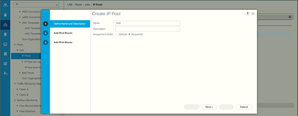
Step 3 – IPv4 IP Address Block: Now we need to create an IP address block for out-of-band management connectivity to the servers. To create an IP Address Block, navigate to LAN > expand Pools > expand root > right-click IP Pools > select Create IP Pool.
Enter the name and assignment order for the IP Pool and click Next. In the next screen, you would be required to click the Add button to enter the IPv4 block and click Finish. UCS Manager also provides you the option of adding an IPv6 block if your environment supports it.
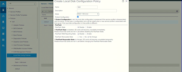
Step 4 – Local Disk Configuration Policy: The Local Disk Configuration Policy will determine the RAID configuration for the Direct-Attached Storage (DAS). To create a Local Disk Configuration Policy, navigate to Servers > expand Policies > expand root > right-click Local Disk Config Policies > select Create Local Disk Config Policy.
In the Local Disk Configuration Policy window, enter the name and configuration mode of the policy. Since we’re using B200 M5 servers in this scenario which can accommodate up to two drives, we have selected RAID 1 Mirrored. It supports multiple RAID configuration options which you can choose if you’re using a full-width blade server or rack server. Once done, click OK to create the policy.
Step 5 – Host Firmware Package: The purpose of creating a Host Firmware Package is to maintain an identical firmware version across all the hosts that will be associated with these service profiles in your environment. To create a Host Firmware Package for your blade server, navigate to Servers > expand Policies > expand root > right-click Host Firmware Packages > select Create Host Firmware Package.
One the Host Firmware Package configuration window, you would be given two options – simple or advanced. The simple option lets you select the blade and rack package version and gives you a list of components that you would want to exclude from the firmware package policy. Whereas advanced options let you create a very granular policy, giving you the option to select the firmware for each type of VIC, FC adapter, CIMC for every blade server, etc. we have gone with the simple configuration option as illustrated in the screenshot below:
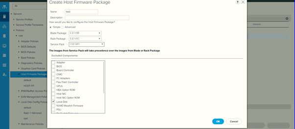
Please note that the package version of all the bundles should match otherwise it will throw an error while trying to create the firmware package policy.
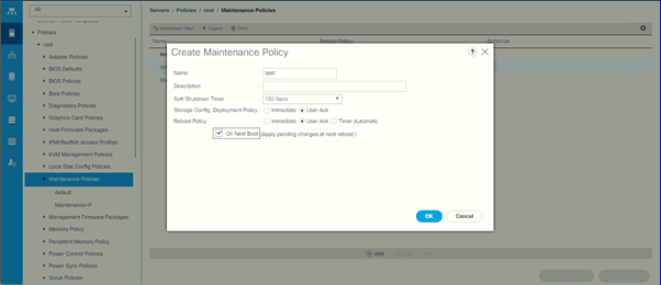
Step 6 – Maintenance Policy: A Maintenance Policy determines the kind of behavior to be exhibited when there is any disruptive change made to the service profile associated with a blade server. To configure a Maintenance Policy, navigate to Servers > expand Policies > expand root > right-click Maintenance Policies > select Create Maintenance Policy.
The User Ack option defines the requirement for manual user acknowledgment. For example: if any changes were made to the service profile, then the server would wait for user acknowledgment in our case as justified in the screenshot below and the changes would be applied on the next boot. If you would select Immediately, then the server would reboot immediately when the changes are applied to it. Timer Automatic option would ask you to choose a schedule to reboot the server during a specific time of the day.
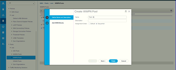
Step 7 – WWPN Pool: WWPN Pool will be used by the Fibre Channel vHBAs in the blade servers to connect to the SAN. There are two types of pools that can be created:
- WWPN Pool – This will be the port name assigned to the vHBA
- WWNN Pool – This will be the node name assigned to the blade servers.
To create a WWPN Pool, navigate to SAN > expand Pools > expand root > right-click WWPN Pool > create WWPN Pool. On the WWPN creation window, you would be required to enter the name and assignment order for the WWPN Pool and click Next. In the next screen, click Add button to enter the range for WWPN to be assigned to the pool and click Finish.
You would require creating two WWPN Pools, I.e., one for vHBAs connected to the Fabric Interconnect-A and another one for the vHBAs connected to Fabric Interconnect-B. repeat the same process to create a WWPN Pool for Fabric-B vHBAs.
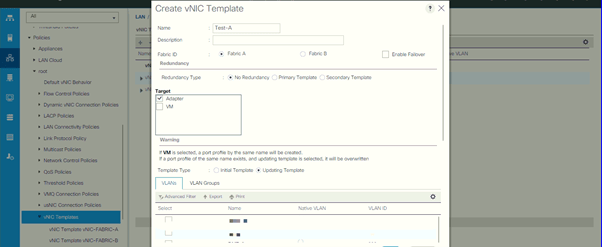
Step 8 – vNIC Template: A vNIC template policy would define how a vNIC on a blade server would connect to the LAN. We will be creating vNIC templates and we will bind those vNIC templates with Fabric IDs, which means that each vNIC will have a dedicated path to the fabric via their respective Fabric Interconnects. To create vNIC template, navigate to LAN > expand Policies > expand root > right-click vNIC Templates > select Create vNIC Template.
At the vNIC configuration window, you would be required to enter the name for your vNIC Template, select the Fabric ID. We have not enabled failover to allow vNIC-A to be able to talk to Fabric-B. Select Updating Template to enable your template to be able to make changes when the service profile is edited. Along with this information you would also want to key in information like VLAN, MAC Pool, MTU, etc.
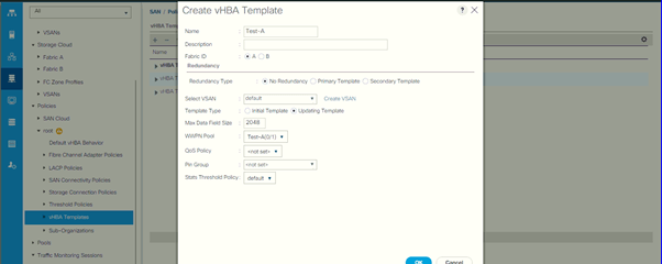
Step 9 – vHBA Template: A vHBA Template policy would define how a vHBA on a blade server would connect to the SAN. We would be creating two vHBAs, just like we created two vNICs. Both vHBAs will be connected to their respective Fabric IDs. To create a vHBA Template, navigate to SAN > expand Policies > expand root > right-click vHBA Templates > select Create vHBA Template.
On the vHBA Template creation window, you would be required to enter the name of the vHBA Template, select a Fabric ID where your vHBA will connect to, and select the WWPN pool which you created for the specific Fabric ID. You can also choose to fill extra configuration parameters like QoS Policy, Pin Groups, etc. Repeat the same steps to create a vHBA template for Fabric-B.
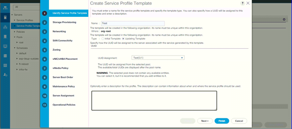
Step 10 – Create a Service Profile Template: Now that we have all the configuration in place, we can go ahead and create a Service Profile Template and derive service profiles for our servers. To create a Service Profile Template, navigate to Servers > right-click Service Profile Templates > Create Service Profile Templates.
On the Service Profile Template creation window, you would be required to key in all the information which we have configured until now. On the first page of the configuration window, enter the name of the template and select the UUID Suffix Pool from the drop-down menu and click Next.
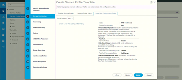
In the next screen, you would be taken to the Storage Provisioning configuration window where we’ll select our Local Disk Configuration Policy and click Next.
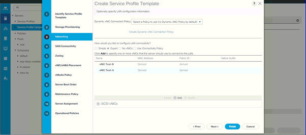
On the Networking configuration window, select the Expert configuration mode and click the Add button. A new configuration window will open where you will be asked to create a vNIC. Click the check box “Use vNIC Template”. A new window would open from where you can select the vNIC template for Fabric-A. Repeat the same procedure to add the vNIC template for Fabric-B.
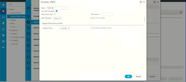
Once added, both the vNICs should appear in the Networking section as illustrated below in the screenshot:
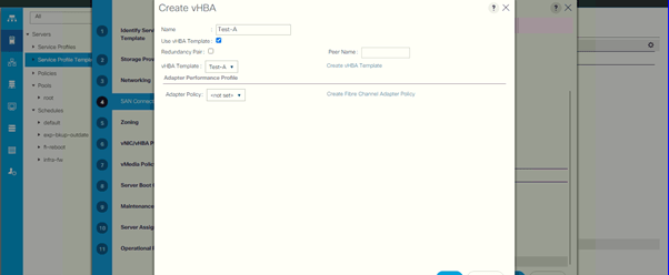
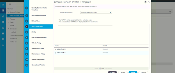
On the next screen, we will be doing the vHBA configuration in our template. We will be creating vHBA from the template just the way we did in creating vNIC from the vNIC template. Select the Expert mode on the SAN connectivity page and click Add button. On the next screen select Use vHBA Template check box. On the new window Enter the name for your vHBA and select the vHBA template.
Once both the vHBAs are added to the template then they should reflect under the Service Profile Template configuration window as illustrated below in the screenshot:
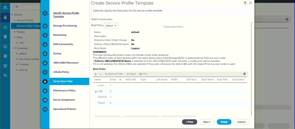
On the next screen, select the Server Boot Order. We have selected the default server boot order. The same screen also provides you with the option to Create a Boot Policy if you have specific requirements when it comes to boot orders.
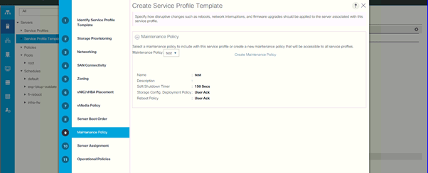
Select the Maintenance Policy from the drop-down menu on the next screen to bind it to the template.
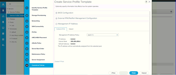
We would skip the Server Assignment tab for now because we will assign the template to servers at a later stage. In the Operational Policies page, select the BIOS policy, if configured. Expand the Management IP Address and select Outbound IPv4, select the IP block pool from the drop-down menu, and click Finish to configure the Service Profile Template with all the information keyed in by us.
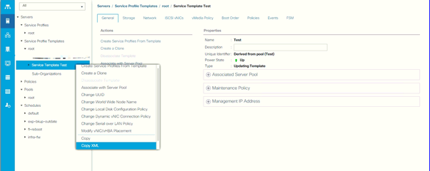
Now that we have successfully created a Service Profile Template, we can generate Service Profiles from the template and assign them to the servers. To generate a service profile, navigate to Servers > expand Service Profile Template > expand root > right-click the Service Profile Template > select Create Service Profiles From Templates as shown in the image below.
Enter the prefix name, suffix number, and the number of instances of service profile you require and click finish. To apply the Service Profile to a blade server, navigate to Equipment and locate a blade server, click Associate a Service Profile in the work-pane and select the service profile that you just created.
To sum it up, these were the ten broad yet simple steps to configure your UCS environment service profiles to take advantage of stateless computing. Zindagi Technologies possesses a diverse roster of professionals who excels in Planning / Designing / Implementation / PoC services for SDDC solutions. If you’re looking for professional services to plan your environment better, let’s get in touch or you can give us a call at +919773973971.
Author
Sumit Yadav
Data Center Consulting Engineer