Brief Introduction and Implementation of MSTP (Multiple Spanning Tree Protocol)
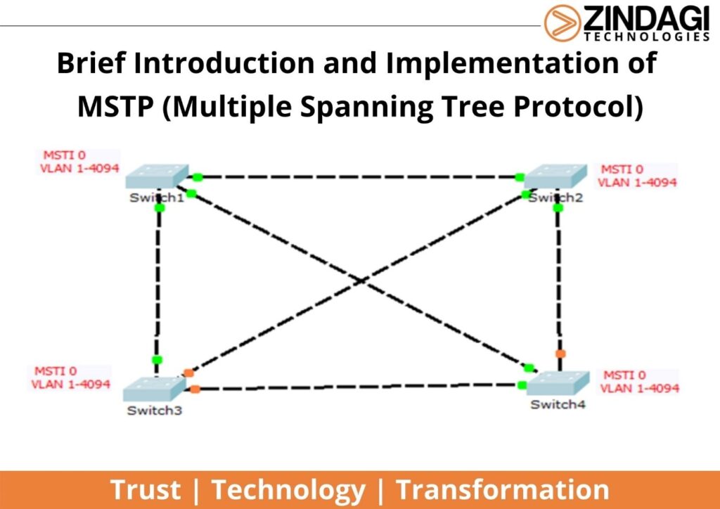
MSTP is an advanced type of STP (Spanning Tree Protocol). Multiple spanning tree protocol (MSTP) is an open standard Layer 2 protocol developed by IEEE [802.1s]. It is backward compatible with STP and RSTP (Rapid Spanning Tree Protocol). In this blog, we will know about MSTP in detail and how to configure it.
What are the benefits Of MSTP?
- Fast convergence: MSTP work on the same mechanism as RSTP (Rapid Spanning Tree Protocol).
- Loop avoidance: Like other STP types, MSTP avoids loops on layer 2 by blocking the port.
- Load Balancing: By making different switches as the root bridge for multiple MST instances, we can provide load balancing.
- Low CPU utilization: MSTP uses a single BPDU format for all MSTP instances for all STP information, this mechanism does reduce the number of BPDUs (Bridge Protocol Data Unit), so CPU utilization is low for MSTP as compared to other STP types. Root Bridge generates the BPDU every 2 Seconds.
What terminologies are used in MSTP?
Common Inter Spanning Tree (CIST)
Common inter-spanning Tree (CIST) is unique for regions. IST and CST elect a Root Bridge for CIST (Common Root Bridge). It takes the responsibility to generate the BPDU & communicate with other MST regions.
Multiple Spanning Tree Instances (MSTI)
MSTP uses instances instead of individual VLAN, this is called Multiple Spanning Tree Instances (MSTI). You are allowed to create multiple MSTI (Support up to a maximum of 16 MSTI) and use the instance number range 0 – 4094.
Internal Spanning Tree (IST)
When the switch configures for MSTP operation, by default, all VLAN is mapped to single instances known as MSTI 0 or IST (Internal Spanning Tree).
Common Spanning Tree (CST)
The CST is a single spanning Tree that connects all MSTP regions in a switched network.
MSTP Port Roles
- Root Port (RP): Nearest port to the Root Bridge (Minimum Path cost to reach Root Bridge). The root port of the switch sends the data to the root bridge. The root Bridge does not have any root port.
- Designated Port (DP): Responsible to send the BPDUs to the downstream devices. Root bridge has all designated ports.
- Master Port Provides connectivity from the local MST Region to the Common Root Bridge (The shortest path to the Common Root Bridge). The root port on the CIST is also the Master port for all MSTI.
- Alternate or Backup: It is the backup port for a root port or master port. It provides an alternate path to the root bridge.
- Edge Port: This port is directly connected to end devices or hosts, but is not connected to any network devices.
Election of Root Bridge, Root port, and Designated port
Root Bridge, Root port, and Designated port election criteria are the same as STP/RSTP. The only difference is while calculating Bridge ID (Priority + Base Mac Address), VLAN ID does not add into priority as STP/RSTP, here Instance Number is added with the priority value.
Bridge ID = (Priority + MSTP Instance Number) + Base Mac Address
If Switch 1 has Instance 2 with VLAN (1-10) mapped, then
Bridge ID = (32768+2) + 0001.4283.9999 = 32770 + 0001.4283.9999
MSTP Regions
MSTP works on the concept of regions. These regions consist of multiple switches among them having the following characteristics:
- Name
- VLAN mapping to instance
- Revision Number
These characteristics are known as MST attributes.
What are the type of MSTP Regions?
On basis of these attributes, there are two types of MST Regions which are the following:
- Intra Region
- Inter Region
1. Intra Region
A region in which a group of switches has the same attributes is known as Intra Region.
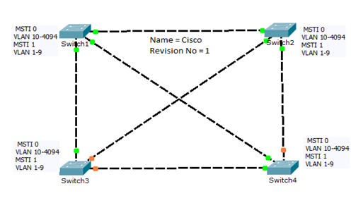
In the figure, all switches in the network have to save attributes, so all switches come in the same region.
2. Inter Region
When switches do not have the same attributes, this is known as Inter Region.
In the figure, switch 1 and switch 3 have the same attributes but differ from Switch 2 and Switch 4 because switch 2 and switch 4 have different attributes (VLAN mapped to different instances).
How MSTP works
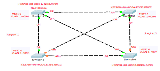
At the start, all switches function as a root bridge and generate the BPDUs, and in the region, the election of the root bridge is done as STP/RSTP. MSTP uses a single BPDU for all MSTI. Multiple MST regions interconnect by CST. MSTP BPDU carries an MST extension header that includes the name of the MST Region, its Config revision number, and a hash value. The hash value is made from the VLAN to MSTI mapping information. First-time switches send the BPDU with MST extension outside the region, but when they receive the BPDU with a different hash value, Switch does not add the MST extension in BPDU, it only sends the IST BPDU (MSTI 0 BPDU). Here IST lower Root Bridge ID switches will become the Common and Internal Spanning Tree (CIST) root switch among all the MSTP regions. Since in figure, Switch1 in Region 1 has lower STP priority than another region switch it is elected as CIST Root over all regions. Switch Switch2 is elected as CIST Regional Root for Region 2 because it has the lowest external Root Path Cost to reach the CIST Root Switch and makes a loop-free topology.
How to configure MST on a switch
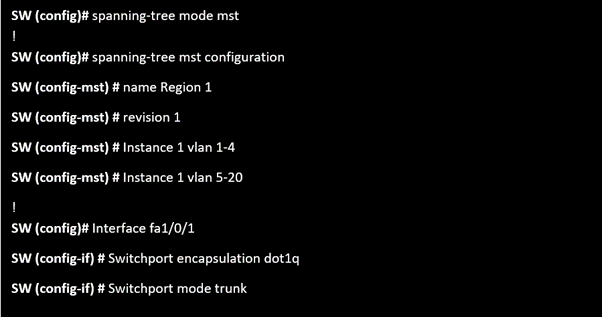
Configuring MST Instance Parameters
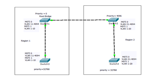
How to change the priority of the switch
Method 1. Manually
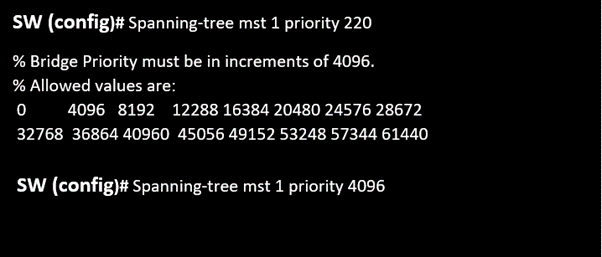
Note: Priority should be chosen in the multiple of 4096 from range 0 to 61440.
Method 2: Using Primary/Secondary

When you configure a switch as a Primary root, the switch sets its own priority for the specified instance to 24576 by decreasing the 8192. But if any switch has a switch priority lower than 24576, the switch sets its own priority to 4096 less than the lowest switch priority.
When you configure a switch as a Secondary root, the switch sets its own priority for the specified instance to 28672 by decreasing the value of 4096. The switch is then likely to become the root switch for the specified instance if the primary root switch fails. But other network switches do not have the switch priority below 28672.
How to change Port Priority
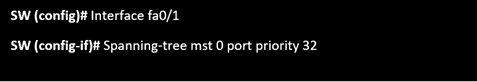
The default is 128. The lower the number, the higher the priority.
The priority values are 0, 16, 32, 48, 64, 80, 96, 112, 128, 144, 160, 176, 192, 208, 224, and 240.
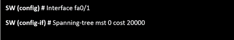
How to change Path Cost
Zindagi Technology is a leading IT consulting company in Delhi. We have successfully completed a lot of projects in the Public and Private sectors. We provide IT solutions like cyber security, planning, designing, and implementation of data centers, cloud-based services, application development, etc. we can assist you in your network programs. If you require any support, Please Contact us or send us a message on +91-9773973971 or drop us an inquiry email.
Author
Shobhit Garg
Associate Consultant