HOW IS THE TRAFFIC FLOW IN ACI (Application Centric Infrastructure)?
Before moving forward to see how traffic flows in the ACI environment let’s have a look at a few terminologies which are required to understand the traffic flow.
What Are Endpoints?
Endpoints are the devices/host which is connected to the fabric. In ACI endpoint can be represented by MAC or IP with /32 masks.
There are two types of endpoints which are local endpoints and remote endpoints.
- Local Endpoints: – Endpoints that are directly connected to the leaf switch. These reside in the endpoint table. If the leaf switch receives a packet on the front panel port which needs communication in the same subnet, it will save only the mac information. If the communication is routed or it is an ARP packet, then both IP and mac will be saved in the endpoint table.
- Remote Endpoints: – Endpoints that are learned via the tunnel interface connected to some other leaf switch are considered remote endpoints. These also reside in the endpoint table.
What Are The Different Forwarding Tables In ACI?
- Endpoint Table: – It contains host information like MAC or IP + MAC with /32 masks.
- Routing Table: – It contains mainly non /32 routes except for /32 for SVI under Bridge Domain and L3Out route. Subnet under BD will be injected by ACI fabric into the routing table as /32 route and routes which are outside the network and those which are /32 are injected by ACI fabric into the routing table as /32 route.
- ARP Table: – It has information only for L3Out.
Local Endpoint Learning Process
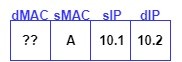
STEP 1: – Switch receive the packet with source Mac A and source IP B.
STEP 2: – If the received packet is an ARP packet or a routed packet leaf will learn the Mac and IP address of the endpoint else it will learn only the Mac address.
STEP 3: – Leaf will send this endpoint information to the spine via COOP Protocol and all spines will sync this information.
Remote Endpoint Learning Process
When a packet enters a Cisco ACI leaf switch from another leaf switch via a spine switch, Cisco ACI learns a MAC or IP address as a remote endpoint.
Step 1: – Switch receive the packet with source Mac A and source IP B from the spine switch.
Step 2: – Switch learns mac A as a remote endpoint if the VXLAN contains bridge domain information.
Step 3: – Switch learns IP B as a remote endpoint if the VXLAN contains VRF information.
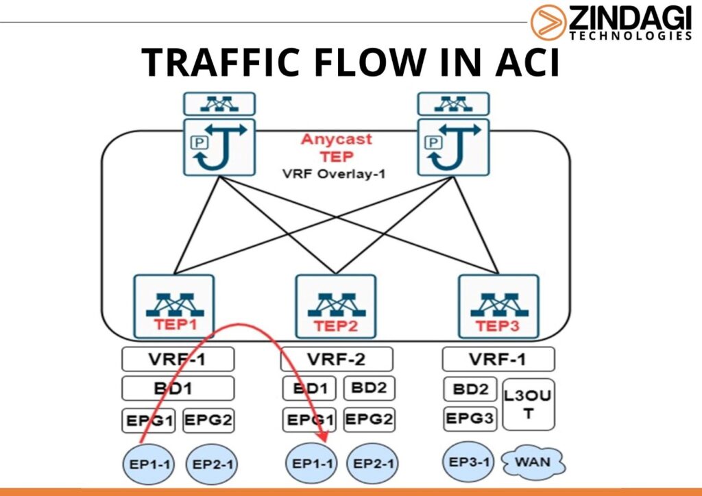
STEP 1: When EP1-1 generates an ICMP traffic for EP1-2 which are in the same EPG. Due to the unavailability of EP1-2 Mac, EP1-1 generates the arp request to know the mac mapped against EP1-2 and when it reaches the Leaf-1, Leaf-1 learns the IP address, Mac and port at which EP1-1 is connected in the endpoint table and inform the Spine about local endpoint through COOP Protocol.
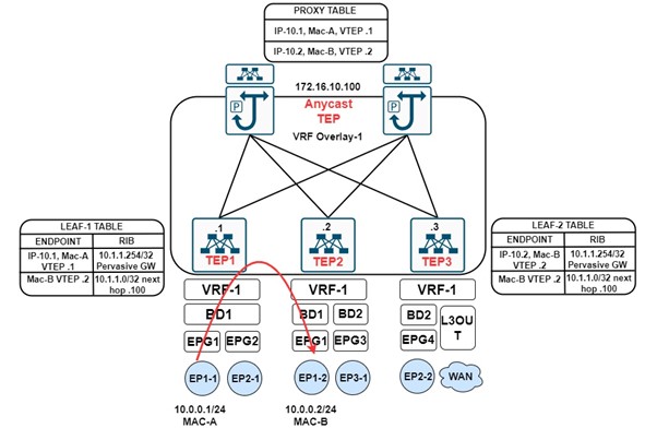
STEP 2: As the leaf receives traffic from the front panel, it takes the forwarding decision by first looking at the entry in the endpoint table, if no entry is present for the destination IP VTEP, it then checks the Routing Table and there is an entry (Pervasive route) for the subnet to which destination IP 10.1.1.2 belongs towards the anycast TEP address of the Spine. Considering ARP flooding is disabled under Bridge Domain.
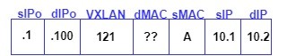
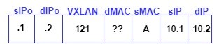
STEP 3: Leaf-1 will encapsulate the packet before sending it to the Spine with the VXLAN header. In the VXLAN header information about the Source EPG and either the BD or VRF VNI is added. If the traffic is L2 (within the same subnet) BD VNI is added and if the traffic is L3 traffic (between different subnets) VRF VNI is added. It adds in the external header with the source IP of VTEP1 and destination IP of anycast TEP of Spine. As the communication here is between endpoints of BD-1, therefore BD-1 VNI is added.
STEP 4: When the Spine receives the traffic, the packet gets dropped as there is no entry in the Spine about EP1-2. Spine now generates the ARP Glean packet towards all the leaf switches for the destination IP 10.1.1.2 of EP1-2. The leaf on which the BD with an associated subnet of destination IP matches accepts the packet and the rest drops the packet.
STEP 5: The Leaf which accepts the packet, sends the ARP request toward the downlink port. EP1-2 gives the ARP response to Leaf 2 and Leaf 2 updates its endpoint table and informs the same via COOP to the Spine.
STEP 6: Now when the Leaf-1 receives the ARP Request from EP1-1 it will send it to Spine which will now rewrite the packet with the destination IP from its VTEP anycast to Leaf-2 VTEP IP. Leaf-2 on receiving the packet learns the Source MAC address as in the VXLAN header BD VNI is added. Leaf-2 de-capsulate the outer header and forwards it to the EP1-2.
STEP 7: EP1-2 on receiving the ARP Request, forward the ARP Response towards the Leaf-2. Leaf-2 will take the forwarding decision by matching the entry in the endpoint table and will encapsulate the packet in VXLAN and forward via the tunnel.
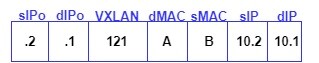
STEP 8: Leaf-1 on receiving the packet learns the remote endpoint information. In these cases, Leaf-1 learns the source MAC as in VXLAN BD VNID is populated. Leaf-1 decapsulates the outer header and forwards it to EP1-1.
Zindagi Technologies is a top IT consulting and cybersecurity company in Delhi having engineers with decades of experience in planning, designing, and implementing Data Centers. Our other services include Managed IT Services, cybersecurity, Data Centers, Audits and assessments, and cloud services. If you want to secure your network or your IT infrastructure then you can contact us and we will handle the IT and will help you in achieving business goals. Please ping us at +91-9773973971 or drop us an email so we can have a discussion and decide what is best for you. To get the latest updates on our tech blogs and other stuff follow us on LinkedIn.
Author
Jainul Khan
Associate Consultant
Fabric Discovery Process in ACI | Zindagi Technologies
December 8, 2022[…] provisioned through the APIC. Multiple ACI fabrics may exist within the same data center, and each ACI fabric may have its own APIC cluster and Cisco Nexus 9000 Series switches. Each switch must be registered […]