How To Configure A VLAN On A Port In An ACI Fabric?
In this blog, we will explain how different policies are configured to assign VLAN on a port in an ACI fabric. We do not configure VLAN directly on a port but use policies that will allow us to scale configuration and apply similar behavior to switches or ports.
Let’s see the below use cases where Layer 2 switch is connected to ACI Fabric on port 1/5 of Leaf-1 and Server connected to LACP port-channel are connected to Leaf-1 and Leaf-2 on 1/10 port respectively.
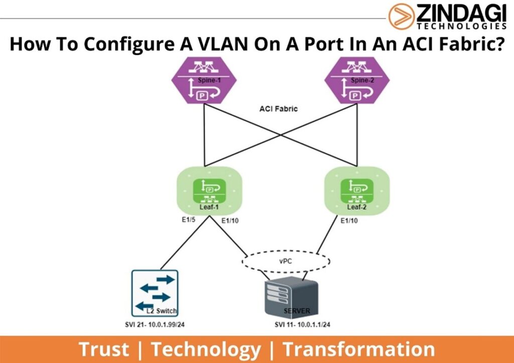
In the above scenario following features need to be configured for the communication.
- Switch Profile
- Interface Profile
- Interface Policies
- Interface Policies Group
- vPC
- VLAN pools
- Domains
- Attachable Access Entity Profile
- Tenant, Application Profile, and EPG
What is a Switch Profile?
Switch Profile defines the switches which need to be configured.
Steps to create Switch Profile
Path- Fabric>Access Policies>Switches>Leaf Switches >Profile >Create Leaf Profile>Right Click
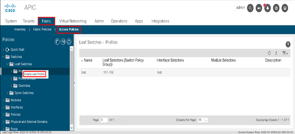
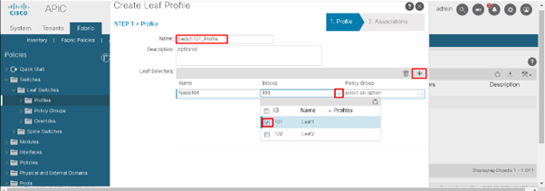
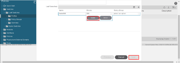
Note: “Switch101-Profile” will be for a switch profile containing node-101 and “Switch101-102_Profile” for a switch profile containing switches 101-102 which are part of a vPC domain.
For the above scenarios, we will create two switch profiles one for Leaf-101 and the other for Leaf-101 and Leaf-102 being part of vPC.
What is Interface Profile?
The interface profile contains 1 or more access port selectors which require the configuration.
Steps to create Interface Profile
Path- Fabric>Access Policies>Interface>Leaf Interface>Profile>Create Leaf Interface Profile>Right Click
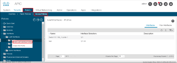
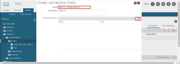
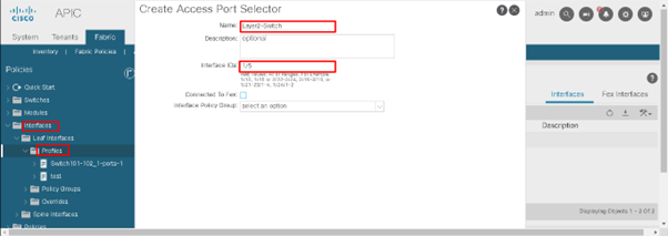
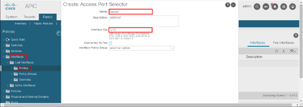
Note: A single interface profile can be created per physical switch and one interface profile for each vPC domain.
Switch101_Profile_ifselector will be the interface profile for per physical switch and Switch101-102_Profile_ifselector for the vPC domain.
What are Interface Policies?
Interface Policies are the characteristics that we can define for the ports in the switch and these interface policies are further called in the Interface Policy Group.
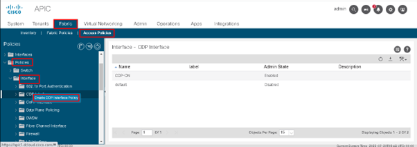
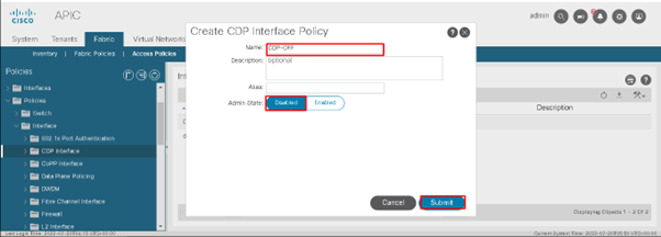
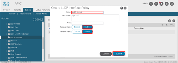
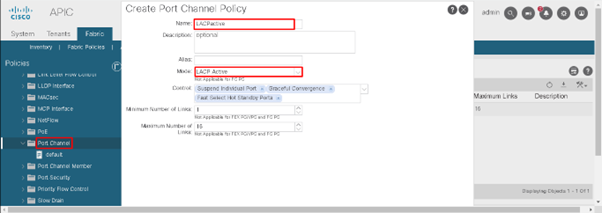
Steps to Create Interface Policies
Path-Fabric>Access Policies>Policies>Interfaces>CDP Interface>Right Click
Similarly make policies such as LLDP, Port-Channel, etc.
Steps to create Interface Policy Group
Path-Fabric>Access Policies>Interfaces>Leaf Interface>Policy Groups>Leaf Access Port>Right Click
Note: Access Port IPG is created for the port which is not a member of the port channel. In the above scenario Access port, IPG will be made for Leaf 101.
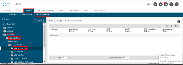
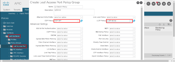
Note: We can select another characteristic too which needs to be deployed on the interface.
Path-Fabric>Access Policies>Interfaces>Leaf Interface>Policy Groups> vPC Interface >Right Click
Note: vPC Interface IPG is created for the port which is a member of the port channel.
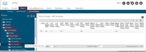
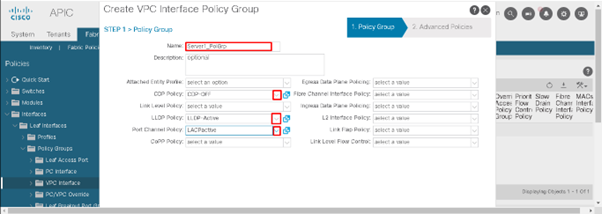
Steps to bind switch profile with interface profile
Path-Fabric>Access Policies>Switches>Leaf Switches>Profile>Select Switch Profile Created
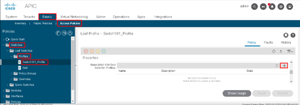
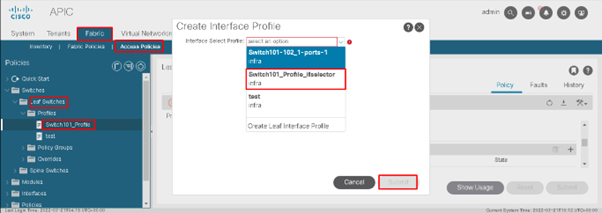
Steps to bind interface policy group with interface
Path-Fabric>Access Policies>Interfaces>Leaf Interfaces>Profile>Select Interface Profile>Access Port Selector
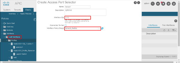
Note- The interface policies which are called in IPG are now bound to the interface which requires the mentioned characteristic.
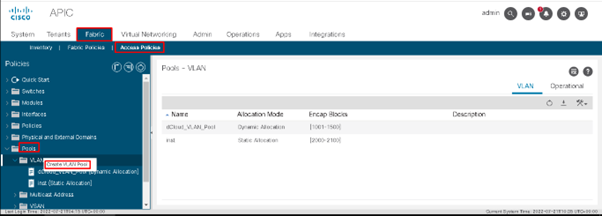
Steps to create a VLAN pool
Path-Fabric>Access Policies>Pools>VLAN>Right Click
Note: Static VLAN pool is created for static deployment and a Dynamic pool is created for dynamic deployment (VMM).
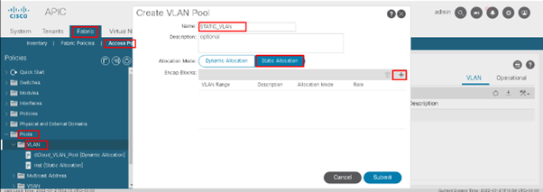
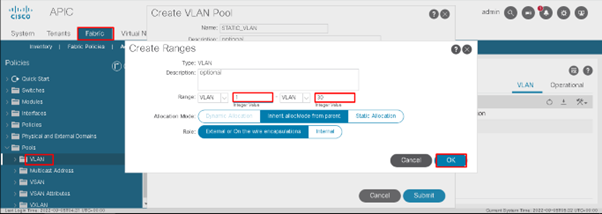
What is Domain?
A domain defines the ‘scope’ of a VLAN pool and where that pool will be used. Physical Domain is used for Bare Metal. For most deployments, a single physical domain is sufficient for static path deployment and one routed domain for L3Outs.
Steps to Create Domain
Path- Fabric>Access Policies>Physical and External Domains>Physical Domains>Right Click
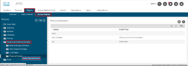
Map the domain with the VLAN pool.
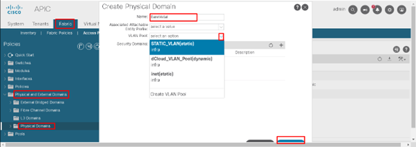
What is AAEP?
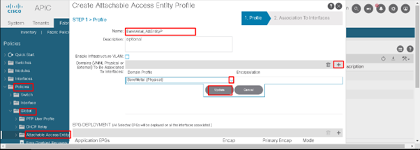
Attachable Access Entity Profile is used to map the domain to the interface policies group with the end goal of mapping VLAN to the interface. Single AEP should be used for static paths and additional AEP per VMM domain.
Steps to create Attachable Access Entity Profile
Path: Fabric>Access Policies>Policies>Global>Attachable Access Entity Profile>Right Click
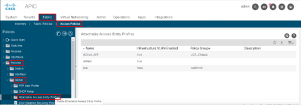
Map AAEP with the domain
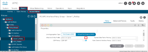
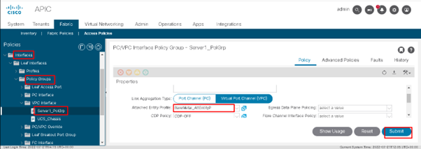
Map AAEP with the IPG
Steps to create a vPC domain and Explicit vPC Protection Group
Path-Fabric>Access Policies>Policies>Switch>VPC Domain>Right Click
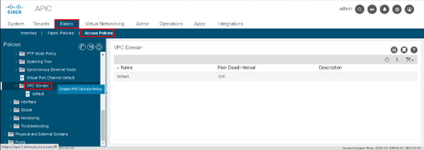
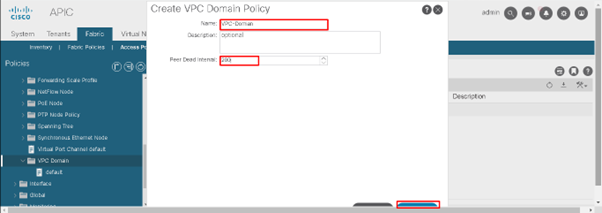
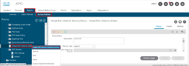
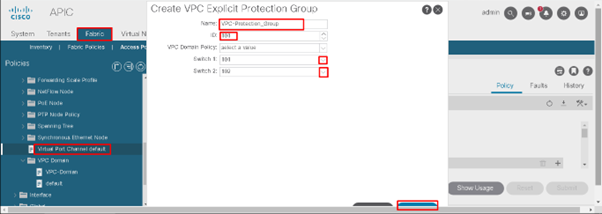
Note– One VPC Domain is created where we define Peer Dead Interval. VPC Explicit Protection Group is created where we call vPC peer device. Once created, a VTEP IP for the peer device is assigned automatically by APIC.
Path-Fabric>Access Policies>Policies>Switch>Virtual Port Channel default>Right Click
What is Tenant in ACI?
Tenant is the main Container of policies where all L2 and L3 policies will be constructed, access rules, and services. It is used for the separation of management. There are two kinds of tenants- user define and pre-defined or default.
Three pre-defined tenants are
- Infra Tenant- It will have policies related to internal fabric communication.
- Common Tenant- It will have policies/services which can be used by the rest of the tenant.
- Management Tenant- It will be responsible for Inband and OOB management.
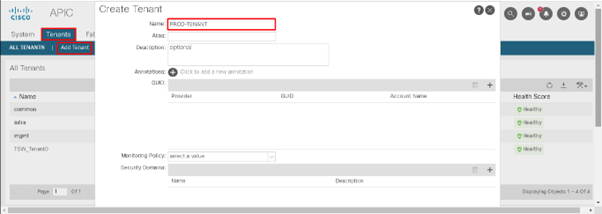
Steps to creating a Tenant
Path- Tenants>Add Tenant>Click>Submit
What is Bridge Domain?
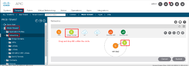
A bridge domain is a container of subnets. Under B.D we define subnet for the VLAN. The bridge domain will be part of VRF and VRF will be part of the tenant.
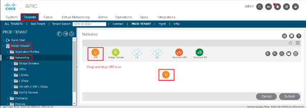
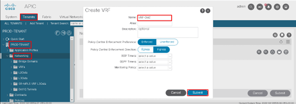
Steps to create VRF and Bridge Domain
Path- Tenants>PROD-TENANT>Networking>Click on it>Drag and drop VRF
Path- Tenants>PROD-TENANT>Networking>Click on it>Drag and drop Bridge Domain
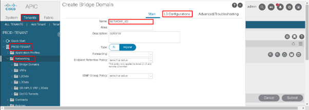
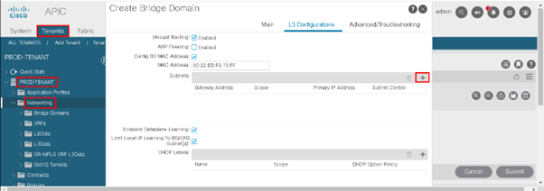
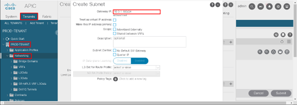
What are Application Profile and EPG?
Application Profile is a container of EPG. It contains one or more EPGs. The Endpoint Group is a logical entity that contains a collection of endpoints that may be in different VLANs or subnets.
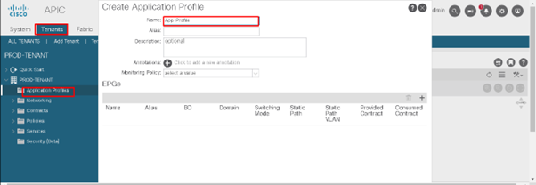
Steps to Create Application Profile
Path- Tenant>PROD-TENANT>Application Profile>Right Click
Note: – Under the application profile, EPG created will be used for the physical domain (bare metal) and VMM domain.
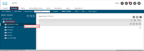
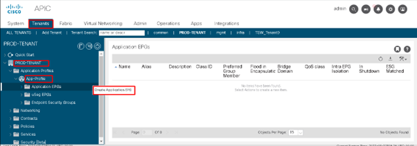
Steps to Create EPG
Path- Tenant>PROD-TENANT>App-Profile>Application EPG>Right Click
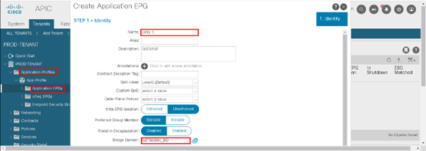
EPG is created and bound with Bridge Domain. The next step is to bind EPG with the domain and bond either with the entire leaf or the ports of the leaf.
Path- Tenants>PROD-TENANT>Application Profile>App-Profile>Application EPG>EPG-1>Domain>Right Click
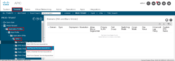
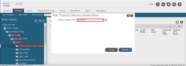
Note: – In the below dashboard static port option within the EPG is used to bind ports to an EPG and the static leaf option within the EPG is used to bind the entire leaf to that EPG.
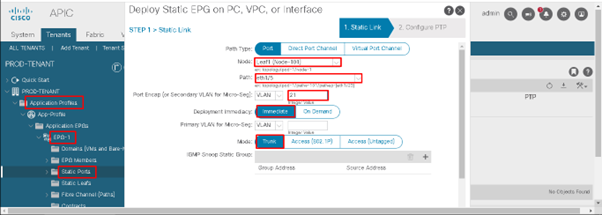
Path- Tenants>PROD-TENANT>Application Profile>App-Profile>Application EPG>EPG-1>Static Ports>Right Click
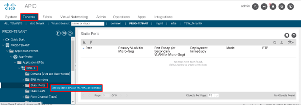
Note: – Mapping VLAN to an individual port of a leaf.
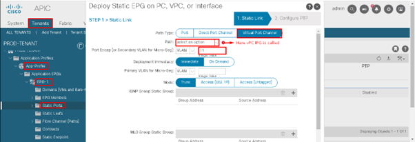
Note: – Static Port binding for the vPC is shown below
In the next blog, we will see how traffic flows between endpoints in ACI fabric. For more information regarding ACI deployment, you can follow Setting Up an ACI Fabric: Initial Setup Configuration Example.
Zindagi Technologies is an IT consulting and cybersecurity company in Delhi having engineers with decades of experience in planning, designing, and implementing Data Centers along with Managed IT Services, cybersecurity, and cloud services. Not just this, we also deal in many other services that will help you in finding out bugs in your IT infrastructure. If you want to secure your network, we are just a call away. Please ping us at +91-9773973971 or drop us a mail. To get the latest updates on our organization, you can follow us on LinkedIn.
Author
Jainul Khan
Associate Consultant

Traffic flow in ACI | Zindagi Technologies
December 7, 2022[…] moving forward to see how traffic flows in the ACI environment let’s have a look at a few terminologies which are required to understand the traffic […]